Electronic product design is an exciting yet challenging process that blends creativity with engineering discipline. Whether you’re building a smart gadget, a custom embedded board, or a new IoT device, the design flow usually follows a similar path. In this blog, I’ll walk you through the key stages of electronic product design—from the initial idea to a working prototype.
1. Start with the Problem – Not the Solution
The very first step in electronic product design is not choosing a chip or drawing a schematic—it’s understanding the problem you are trying to solve.
Ask yourself (or your client):
- What is the real-world problem this product aims to address?
- Who will use it, and in what environment?
- What are the essential features, and what are optional?
This stage shapes everything that comes later—from the screen size, power requirements, and communication interfaces to the overall user experience.
Example Questions to Ask:
- Does it need a screen? If so, how big and what resolution?
- Will it operate on battery? How long should it last per charge?
- Does it need to connect to a other device, mobile app, or cloud service?
- What sensors or input/output ports are required?
- What is the expected cost and production volume?
Tip: Try creating a user scenario before diving into technical specs. Imagine a person using your product and write down each step they take. This reveals hidden requirements early.
Take Smart Home Control Panel for Example:
Imagine you’re designing a Smart Home Control Panel for Home Automation that can Control Switches, Dimmers, Scene Switches, Sockets, Lightings, Curtains, Air Conditioners, Smart Locks, Door Magnetics, Thermostats, Fresh Air Ventilators, PIRs, Water Leakage Sensors, Temperature & Humidity Sensors, Smoke Alarm Sensors, Video Series (IPC/Security Peephole Viewers/Video Door phone ), On-off Controllers, Aromatherapy Devices, Humidifier, Air Purifiers, Water Heaters etc..
•Since our product will be powered by 220V AC, but most SBCs only require 5V DC, we need to integrate an AC-to-DC converter that can step down 110V–240V AC to 5V DC.
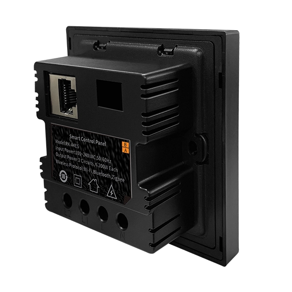
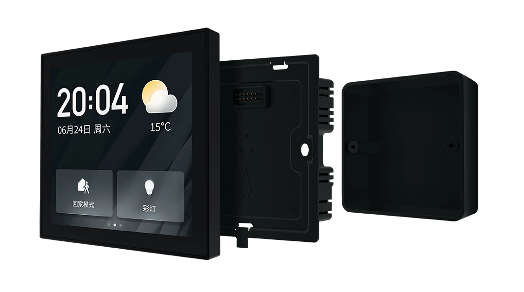
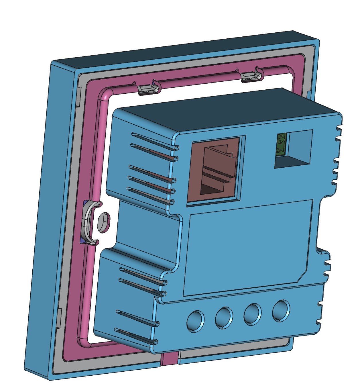
•This product is designed to be installed inside a standard 86-type wall box, allowing it to directly replace a traditional wall switch.To simplify installation, the product is divided into two main parts:
1. The power base box, which is installed inside the wall-mounted 86 electrical box. It includes the AC-to-DC power conversion circuit and provides electrical connections to the front panel.
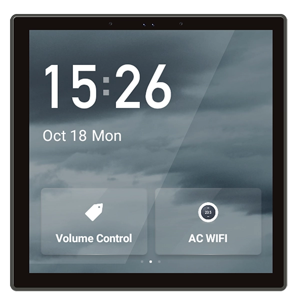
2. The front panel, which is mounted onto the power base box. It contains the display, and other user interface components.
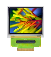
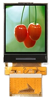
- Considering the size constraints of the 86 wall box, a 4-inch square TFT display with a capacitive touch panel (CTP) was selected as it best fits the available space.
- The product needs to connect to a variety of external devices. Based on our research into their communication methods, we require support for Wi-Fi, Bluetooth, ZigBee, RS485, Ethernet, POE and relays.
- Taking the intended use cases into account, we plan to integrate a speaker, a microphone array, a temperature sensor, a humidity sensor, an ambient light sensor, and a distance sensor.
2. Define the Form Factor and Select Key Components in Electronic Product Design
Based on the requirements defined in Step 1, we can now outline the product’s form factor and core functions, and begin selecting the appropriate components—such as SOC, DDR, Flash, OS, microphones, speakers, ZigBee modules, etc.
This step involves balancing functionality with real-world constraints like physical space, power consumption, cost, and thermal performance. It’s a critical phase in the electronic product design process.
For example:
- If the device needs audio input/output, we must choose a microphone array and a speaker that fit within the enclosure and meet acoustic performance targets.
- For wireless communication, modules such as Wi-Fi, Bluetooth, and ZigBee must be evaluated not only for functionality but also for antenna placement and interference concerns.
- The SBC (Single Board Computer) or main control board must expose the right interfaces (UART, SPI, I2C, GPIO, etc.) to connect with all peripheral components.
At this stage, you also start to sketch or model the mechanical housing. This includes:
- Enclosure size and material
- Placement of connectors and sensors
- Thermal management (e.g. ventilation, heat sinks)
- Assembly method (screws, clips, magnetic mounts, etc.)
💡 Important: If space is limited, you may need to prioritize which features to keep and which to remove.
Example – Smart Home Control Panel:
In the case of the Smart Home Control Panel, we initially planned to include POE, temperature sensor and humidity sensor. However, due to space constraints and the fact that these sensors were not essential to the core user experience, we decided to remove them from the final design.
3. Housing Design, Hardware Prototyping & Firmware Development
With the product concept and components defined, the next phase of electronic product design involves turning the idea into a working prototype—both mechanically and electronically. This includes enclosure design, PCB development, and firmware programming.
🛠️ Housing Design and Prototyping
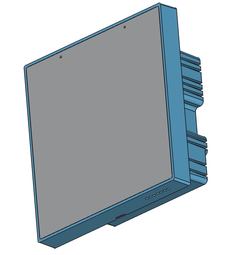
We begin by designing the mechanical enclosure (housing) using 3D CAD software. The housing must accommodate all internal components such as the display, power base, and sensors, while also providing:
- Proper alignment with the 86-type wall box
- Heat dissipation and ventilation
- A secure mounting system (e.g. screw holes, snap-fit structure)
- Aesthetics and material selection (plastic, aluminum, etc.)
To validate the mechanical design, we create physical samples using rapid prototyping methods such as:
- 3D printing for fast, low-cost iterations
- CNC machining for precise and robust parts
- Vacuum casting or silicone molding for small batch verification
These samples are assembled and tested for physical fit, usability, and heat distribution.
🔌 SBC Schematic, Layout & Assembly
Next, we design the Android/Linux embedded boards(SBC) based on the selected microcontroller or SoC. The schematic includes all key components such as:
- Power management (5V DC input, regulators)
- Interfaces: Wi-Fi, Bluetooth, ZigBee, RS485, Ethernet, USB
- Audio: Speaker and microphone array
- Sensors: Temperature, humidity, light, distance
Once the schematic is complete, we proceed with the PCB layout, ensuring good practices in:
- Signal integrity (especially for high-speed lines)
- Power plane design
- EMI/ESD protection
- Compact placement to fit within the 86 box
After fabrication, we assemble the first batch of boards for bring-up and debugging.
💻 Firmware Development and System Debugging
While waiting for hardware or in parallel using dev boards, firmware development begins. Tasks include:
- Porting the operating system (e.g. Linux or RTOS) to the chosen SBC
- Writing drivers for peripherals: display, touch panel, relays, sensors, communication modules
- Implementing communication protocols (e.g. ZigBee, MQTT, RS485)
- Developing the UI logic for the touchscreen (e.g. via Qt, LVGL, or GTK)
- Logging, OTA update support, and fault recovery mechanisms
Once hardware samples are ready, firmware is flashed and tested extensively:
- Power-on and boot sequence validation
- Peripheral function testing (Wi-Fi, relays, UART, etc.)
- Sensor readings and I/O control
- System stability and temperature behavior
This stage results in a fully working engineering prototype, both hardware and software, ready for real-world testing.
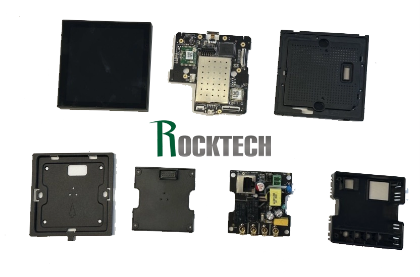
Smart Home Control Panel Sample Components
4. Assembly, Verification, Testing, Tooling, Certification & Launch
With a functional prototype in hand, the final stage of electronic product design focuses on turning that prototype into a reliable, mass-producible product. This includes assembling pilot units, validating all functions, conducting extensive testing, preparing molds, obtaining necessary certifications, and getting ready for market release.
🧩 Assembly and Integration
We begin by assembling complete units using the finalized hardware and enclosure:
- Integrating the power base, SBC, and front panel
- Routing internal cables and connectors
- Securing all parts using screws or snap-fit mechanisms
- Ensuring consistent quality and alignment across samples
This helps identify any assembly issues before scaling up production.
✅ Functional Verification
Each assembled unit undergoes a full functional verification process:
- Boot and power-up sequence
- Display, touch, and UI responsiveness
- Wireless connectivity (Wi-Fi, Bluetooth, ZigBee)
- Wired communication (RS485, Ethernet)
- Sensor accuracy (temperature, humidity, light, distance)
- Audio playback and microphone input
- Relay switching under load
Any discovered issues are logged, analyzed, and fixed in hardware or firmware.
🔁 Testing and Optimization
Before mass production, we perform:
- Aging and stress tests (e.g., continuous 72-hour burn-in)
- Environmental tests (heat, humidity, static discharge, EMI, EMC)
- User testing to evaluate usability and real-world performance
- Field trials for long-term reliability in actual deployment conditions
These results inform the final firmware and mechanical optimizations.
🧳 Tooling and Pilot Production
Once verification is complete, we move to manufacturing preparation:
- Injection mold tooling for the enclosure
- T1 and T2 test runs with visual and dimensional inspections
- Surface treatments like spray painting, texture finishing, or silk-screen logos
- A pilot production batch is built to validate the full assembly process and establish QA procedures
🛡️ Product Certification
To comply with regulatory requirements and ensure safety, we go through necessary product certifications, which may include:
- CE (Europe) – for safety, EMC, and environmental compliance
- FCC (USA) – for electromagnetic emissions
- RoHS – for hazardous substance restrictions
- CCC (China), SRRC, or other region-specific standards depending on the market
These certifications often involve submitting samples to a certified testing lab and making minor design adjustments based on feedback.
Obtaining these certifications is crucial for legal sales and customer confidence, especially in B2B and export scenarios.
🚀 Product Launch
With all tests passed, tooling finalized, and certifications granted, the product is ready for market:
- Final production begins
- Packaging, labeling, and manuals are prepared
- Firmware is version-locked and shipped with production units
- Marketing, sales, and distribution plans are activated
The Smart Home Control Panel is now fully qualified for installation and commercial deployment—a successful example of electronic product design from idea to reality.